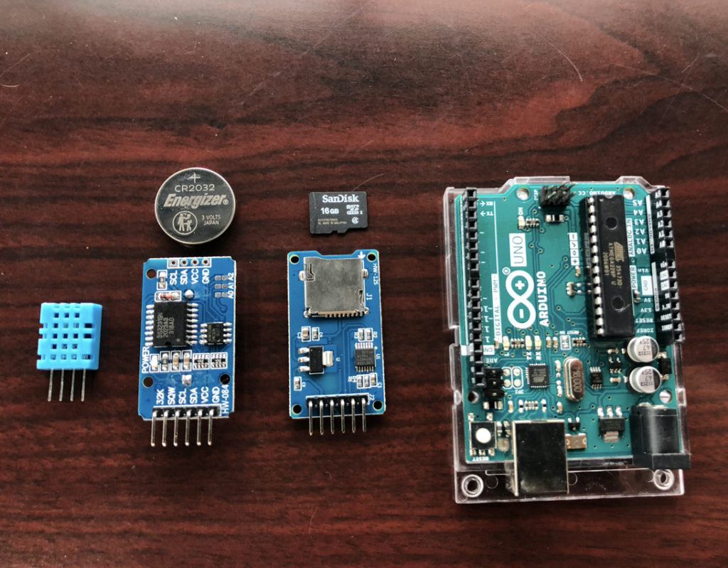
This data logger design is tested by using an Arduino Uno, DS3231 Real Time Clock (RTC) module, an SD card module, and a temperature/humidity sensor. The DS3231 RTC module maintains the date and time, and the DHT11 sensor gathers the temperature and humidity data. The data is saved on an SD card (using the SD card module) for future analysis.
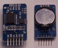
DS3231
The DS3231 is accurate, and it has an internal Temperature Compensated Crystal Oscillator (TCXO), which cannot be affected by high temperatures. It also has a built-in power sense circuit for whenever the main power supply is cut off, the current time and date will still be maintained through the backup power supply. It uses a 3.6V lithium coin cell battery (a CR2032 coin cell battery).
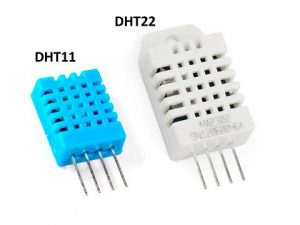
DHT11 Sensor
To test this data logger, it came down to using the DHT11 or DHT22 sensor. The DHT11 and DHT22 are overall the same, but the DHT11 costs less, and the DHT22 can measure temperatures under 0°C (or 32°F). I came to the conclusion that the MROC will not be in use under freezing temperatures.
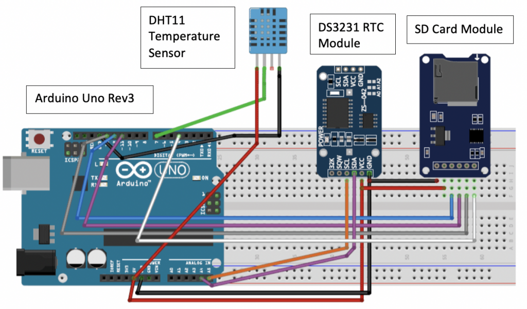
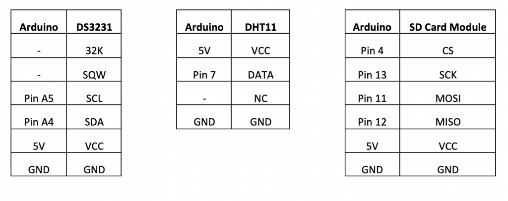
Circuit Diagram
A circuit diagram is used as a reference to build the circuit. The circuit diagram shows the build on a breadboard, with the pin configurations listed below.
Pin Configuration
The DS3231 RTC module uses I2C communication, which requires the SDA and SCL pins. SCL is the clock line, and the SDA is the data line. The SD card module is using Serial Peripheral Interface (SPI) communication, which requires CS (Chip Select), SCK (Serial Clock), MOSI (Master Out Slave In), and MISO (Master In Slave Out). SPI is a serial data protocol used by microcontrollers to communicate with one or more devices in short distances. MISO is the Slave line for sending data to the master, MOSI is the Master line for sending data to the peripherals, and SCK is the clock pulses generated by the master.
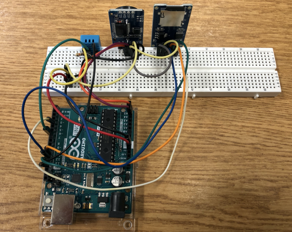
Build
The DHT11 sensor requires a pull-down resistor, so a 10k ohm resistor is added from VCC (pin 1) to output (pin 2). The next post will dive in deeper to the code, and gathering data from both the RTC and DHT11 sensors.
2 Responses
Did you guys thought about choosing another Arduino, such as Arduino Nana or Arduino Mega? or the Arduino Uno is necessary for this project?
The Uno wasn’t required for this project but we did compare it with other microcontrollers in our screening matrix under “Getting Started.” Specifically, I compared mine with the Arduino Pro 3.3V, and this microcontroller is similar to the Arduino Uno. However, the Pro 3.3V is not as versatile as the Uno and it has one regulator. It also runs at 8MHz, which is half the speed of the Uno. The Nano would have been a great alternative to use. As for the Mega, it came down to the cost. The Mega is starting at $40 while the Uno is at $23.
This post will discuss the programming and results for the second test circuit. Existing code that controlled the acceleration of the prototype MROC was used,


2 Responses
Did you guys thought about choosing another Arduino, such as Arduino Nana or Arduino Mega? or the Arduino Uno is necessary for this project?
The Uno wasn’t required for this project but we did compare it with other microcontrollers in our screening matrix under “Getting Started.” Specifically, I compared mine with the Arduino Pro 3.3V, and this microcontroller is similar to the Arduino Uno. However, the Pro 3.3V is not as versatile as the Uno and it has one regulator. It also runs at 8MHz, which is half the speed of the Uno. The Nano would have been a great alternative to use. As for the Mega, it came down to the cost. The Mega is starting at $40 while the Uno is at $23.