This post will discuss the programming and results for the second test circuit.
Existing code that controlled the acceleration of the prototype MROC was used, and data logger code was embedded within it.
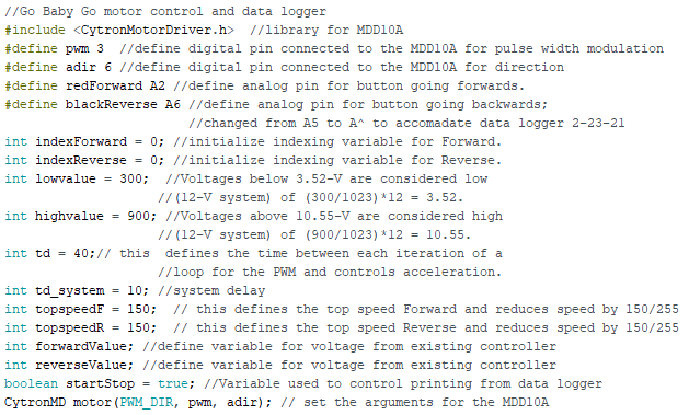
Code
The Cytron Motor Driver libraries needed to be downloaded.
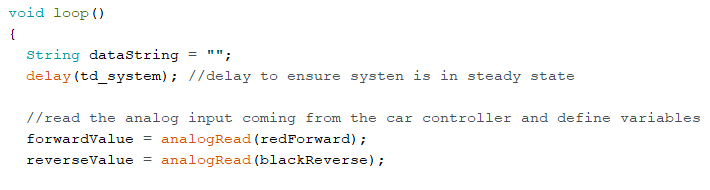
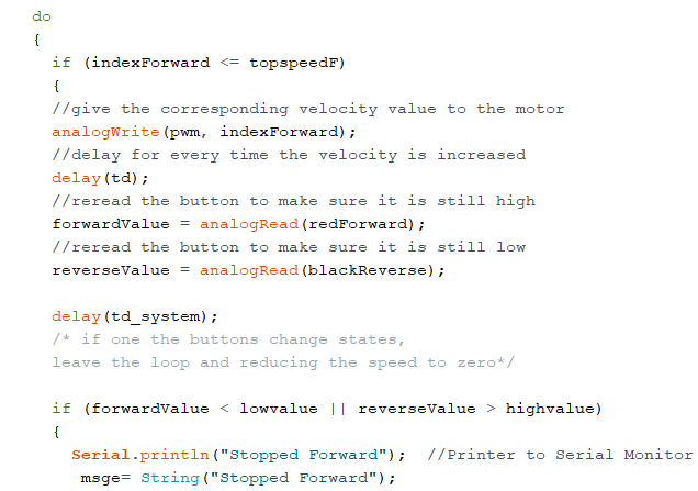
Unlike the previous MROC test circuit (Version 1) that used only digital output pins, this circuit uses both digital analog pins. This is because for the MROC prototype, the vehicle slowly accelerates and decelerates, and therefore, the analog pins would need to be used to simulate that on the test circuit. Using analog pins “redForward A2” and “blackReverse A6” would allow the LED to slowly get brighter when the associated switch was pressed and get dimmer when the switch was off.
This is also contrary to Version 1 where the LEDs just turned on and off automatically.
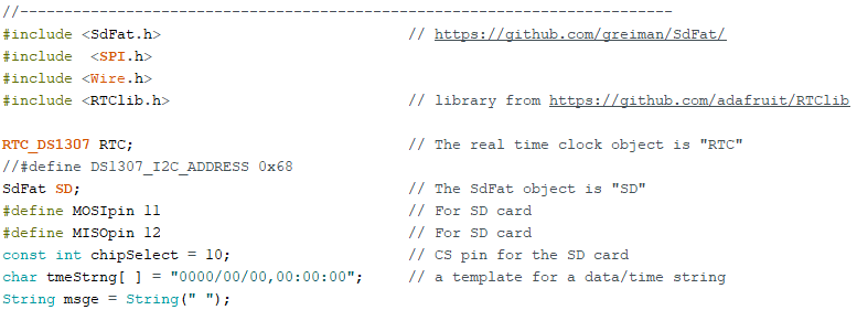
The code is the same for connecting to the built-in SD card.
In void setup the pin modes were set. The motor speed was also set to 0 because there is no motor moving initially, and for the test circuit simulation, there is no motor at all.
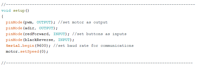
Also in the “void setup” section the program was set to check for the SD card to be inside of the data logger before proceeding. If it was not, the program printed an error and stopped running.
The rest of the void section is the same as Programming and Results – Version 1 and the code can be viewed here: https://gbgdatalogger.ieeecbu.org/2021/02/11/data-logging-with-the-nano-shield-programming-and-results/
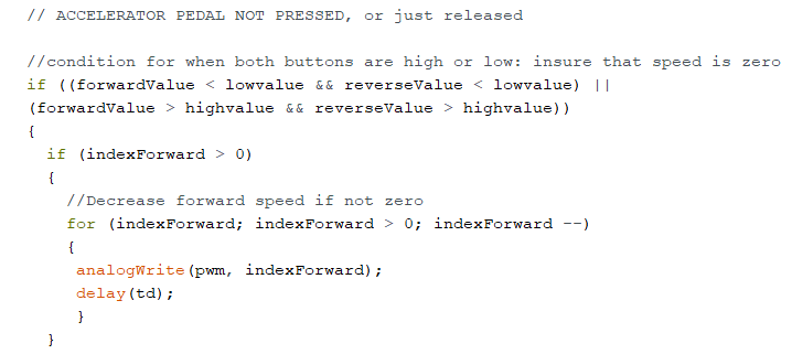
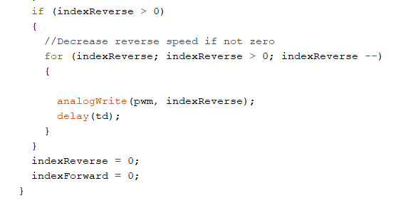
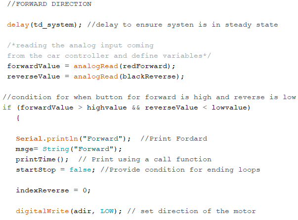
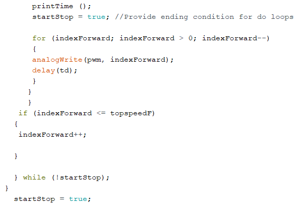
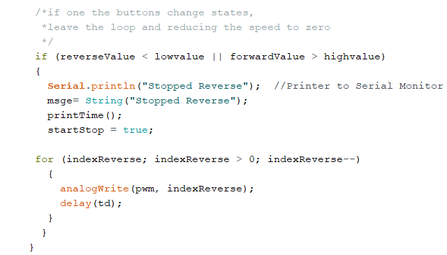
This is the void loop section of the code that deals with the acceleration of the MROC when it is moving forward and in reverse.
The next section of the code is an overview of how the forward motor direction was programmed. It includes code for when the motor is moving and when it stops.
Inside of the button condition for reverse high and reverse low, you will see a variable titled “msge.” This creates a text string to print the associated case (in this case “Forward”) to the data logger’s SD card.
Also, in this section, you will see a call function titled “printTime()”. This function is declared at the end of the program in a void statement and has additional information inside. When the program is running and reaches this function, it will call the void printTime() statement to determine the next steps.
Note: “msge” and “printTime()” appear in each of the four cases (“Forward”, “Forward Stop”, “Reverse”. and “Reverse Stop”).
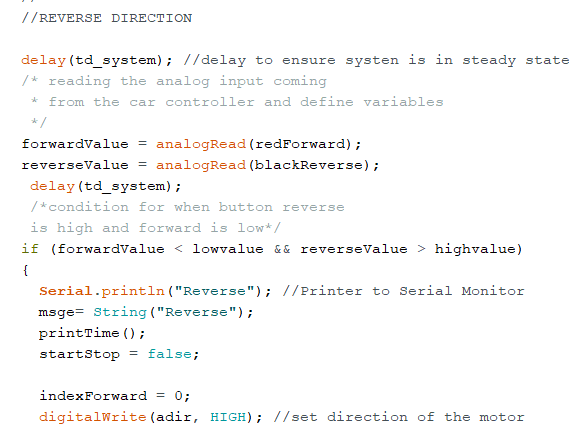
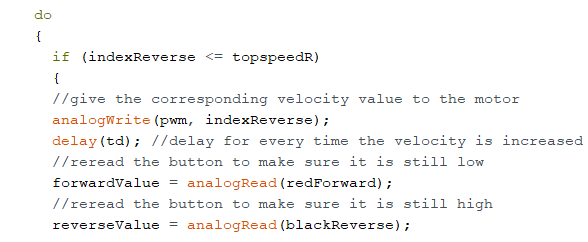
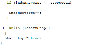
This section depicts the code for the reverse motor direction. It is similar to the code for the forward motor direction.
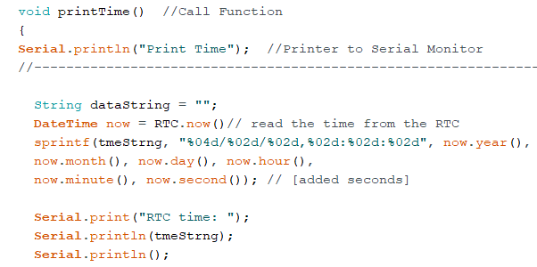
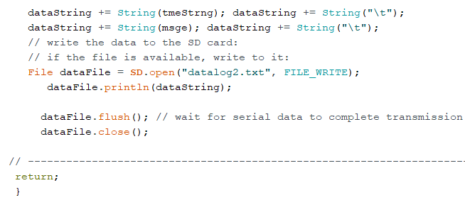
We place the “printTime()” call function in a void statement at the end of the code. The “printTime()” function houses most of the data logger commands required to keep track of the time and direction and store the information on to the text file on the SD card.
By developing a call function, and calling that function within the “Forward,” “Forward Stop,” “Reverse,” and “Reverse Stop” sections of the code, we were able to print the time only when a case took place as depicted in the results section.
This was a major problem that was encountered throughout the testing and programming phases of each device. We wanted to know solely when the MROC began moving forward, when it stopped, and the same for the reverse direction.
In the Test Circuit – Programming and Results – Version 2, we were successful in accomplishing that.
Problems Faced
After the coding portion was complete, it was time to upload it to the Nano.
However, upon uploading, we ran into some difficulty.
The device began to get really hot, and the COM port on the Arduino IDE never recognized the Nano. After careful inspection, it was determined that there was a short in the circuit.
After resolving that problem, we faced another issue. We were able to upload the code, but the LED that was connected to D6 did not turn on when the respective switch was pressed.
We spent a while checking all of the connections. We also took some voltage readings. During these readings, it was concluded that the circuit was functioning as it was supposed to and all of the connections were correct. Therefore, it became apparent that there might be a component issue, such as a resistor.
It turned out that the resistor connected to the D6 LED was the incorrect value, and after replacing that with the correct value, the LED turned on and off as expected.
Results
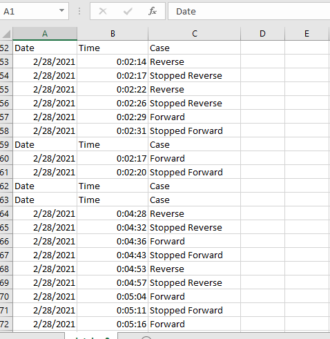
Here is a look at the results of Version 2:
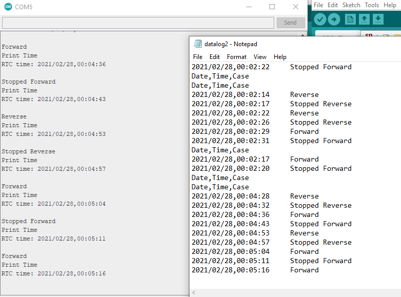
The program prints the time and date that the switch is in a forward case, when it has stopped being in the forward case, and likewise for the reverse cases.
This has been an obstacle for the length of this project, and it was finally able to be overcome.
To expand, the results can simply be uploaded to an Excel file where further analysis can be made. An example is seen below: