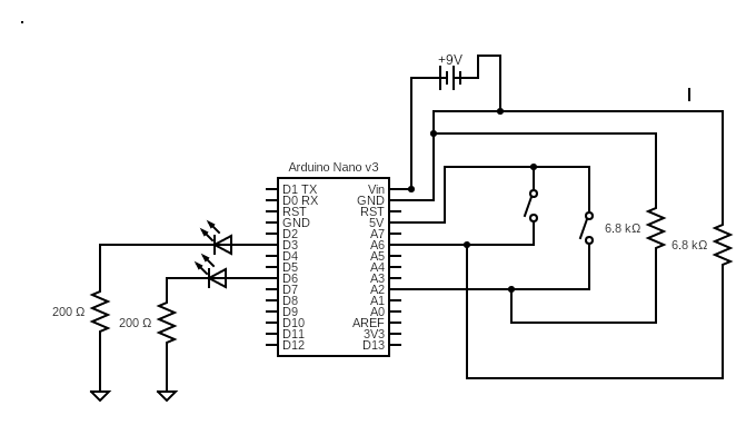
The version 2 test circuit uses the Arduino Nano shield. This test circuit has two 200 ohm resistors in series with the LEDs, two 6.8k ohm resistors, and two switches. The data logger is not shown in this circuit diagram but it is attached to the nano. Also, the USB connection might not supply sufficient power. The nano can work in between 6V-12V DC so we used a 9V DC power supply.
The LED that corresponds to D3 is based on the motor speed.
If the MROC is increasing speed, the brightness also increases. When the LED is fully on, the car reached its max speed.
If the MROC is decreasing speed, the brightness also decreases. When the LED is fully off, the car is at a complete stop.
The LED that corresponds to D6 is based on the motor direction.
If the D6 LED is off, the MROC is moving forwards
If the D6 LED is on, the MROC is moving backwards
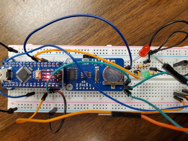
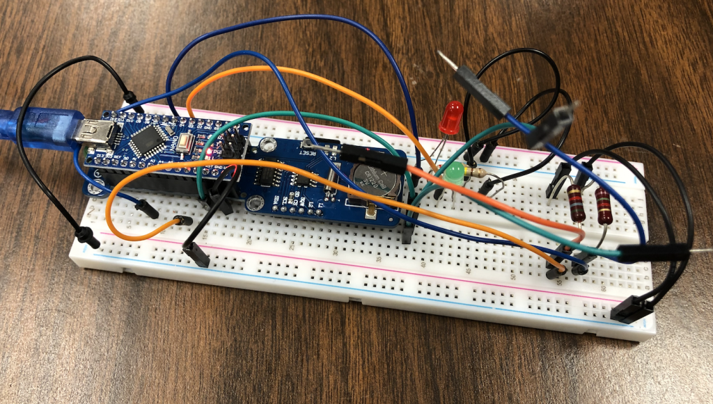
Build
Based on the circuit diagram, this test circuit was built using a green LED, red LED, and the correct resistor values. Also, since we love using jumper wires as switches, we did that with this test circuit as well. The red LED is in series with the D6 pin, and the Green LED is in series with the D3 pin.
This post will discuss the programming and results for the second test circuit. Existing code that controlled the acceleration of the prototype MROC was used,