

To simulate MROC motion in a test environment, a test circuit was created using two LEDs (red and green) and two switches. The switches were connected to the LEDs and when pressed, the LED(s) would turn on and off, respectively.
The idea behind this was that there would be four cases indicating vehicle motion.
4 Cases:
- Both LEDs ON – Vehicle ON, No Motion
- Red LED ON, Green LED OFF – Forward Motion
- Red LED OFF, Green LED ON – Backward Motion
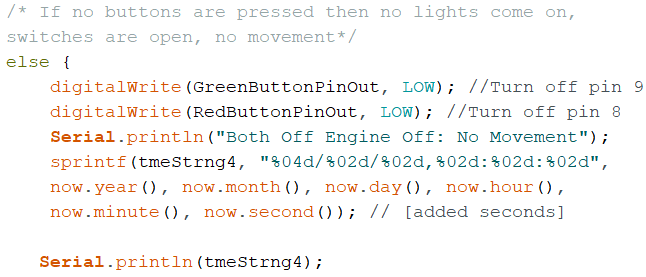
- Both LEDs OFF – Vehicle OFF, No Motion
Programming
Programming the data logger centered around the 4 cases. The goal was to program the logger to print and store the length of time a case took place.
For example, if the red LED was on from 1 pm to 1:37 pm, we wanted a time of 37 mins to be printed and recorded on the data logger’s SD card.
This would need to be done for each case.
As a reminder, the information collected would continuously append to a text file on the SD card. The data could then be transferred to Excel where further analysis could be done by researchers, allowing them to study the child’s interaction with the MROC.
The program is done using a test circuit. Ultimately, the data logger will be installed in the actual MROC prototype.
Process
To begin, the RTC and SDFat libraries were downloaded.
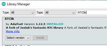
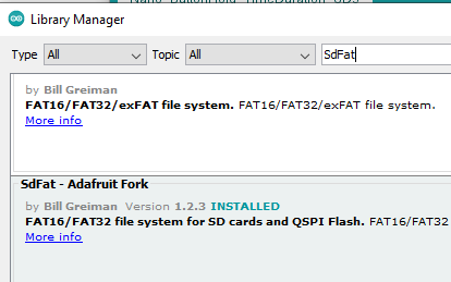
These libraries are needed for the device to communicate with the RTC and SD card.
Now that the libraries were downloaded and installed, they needed to be included in the program as seen below.
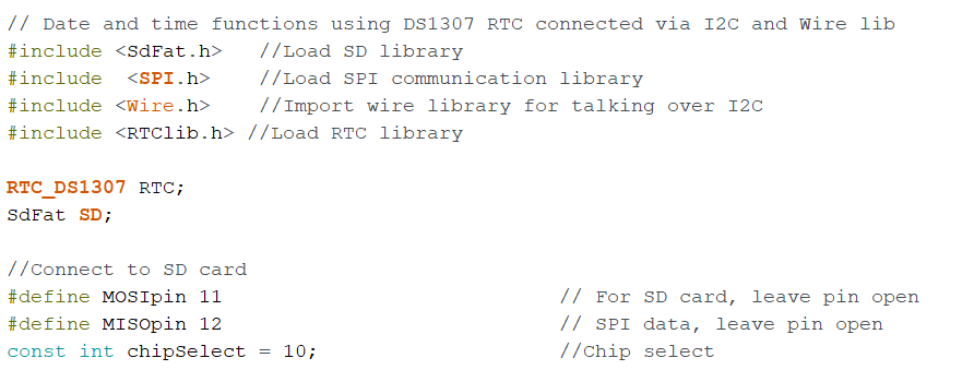
The SPI library and the Wire library also needed to be included, however, these libraries were preinstalled on the device, and therefore, did not need to be installed.
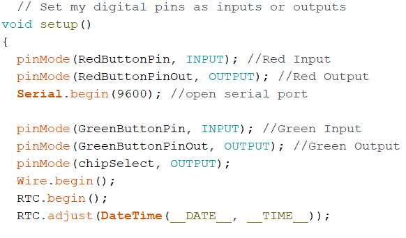
The built-in RTC used was the “DS1307” and needed to be initialized, as well as the “SdFat” SD card.
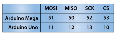
The next step in the code was to connect to the SD card by defining MOSI and MISO pins. The chipSelect also needed to be set to pin 10.
Note: The Arduino Uno and Nano are very similar and use the same pins for SD connection.
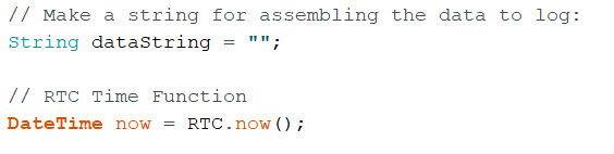
The input and output pins were declared. Four time strings were also declared of “char” type to format the date and time.
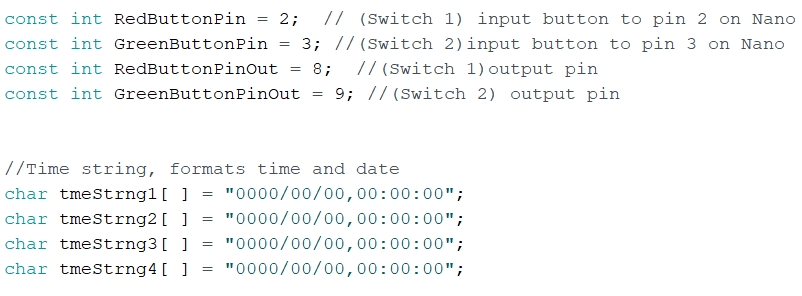
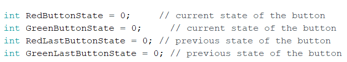
A button state and last button state variable were created for each switch/LED. This was to check for and remember a change in state, or whether a button has or has not been pressed, and to indicate what to do next.
We wanted to know where the button was before and where it was after, so we needed a previous state “(LED)LastButtonState” and a present state “(LED)ButtonState”. If the previous and the present states were different we wanted to switch the position of the LED.
For instance, if the LED was on, turn it off. If it was off, then turn it on.
This section checks to see if an SD card is in the cardholder. If it is, the program continues to run. If it is not, an error is printed to the serial monitor and the program stops.
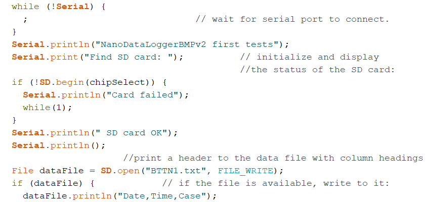
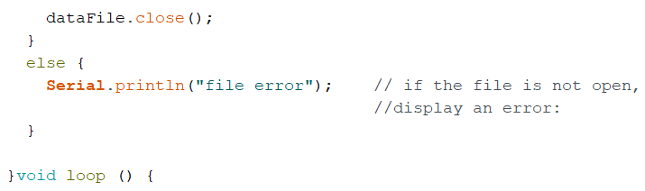
The SD file was opened and ready to collect information.
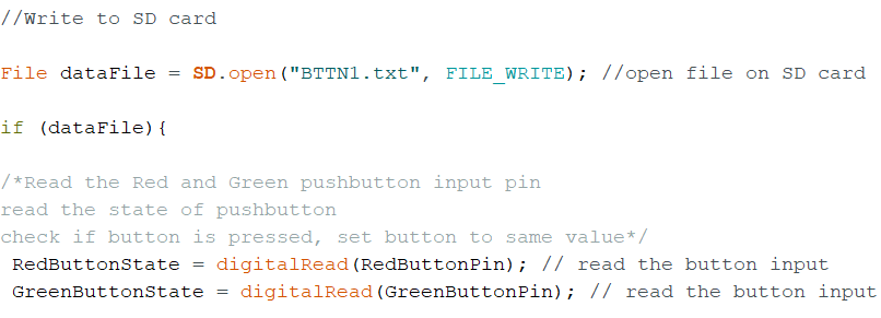
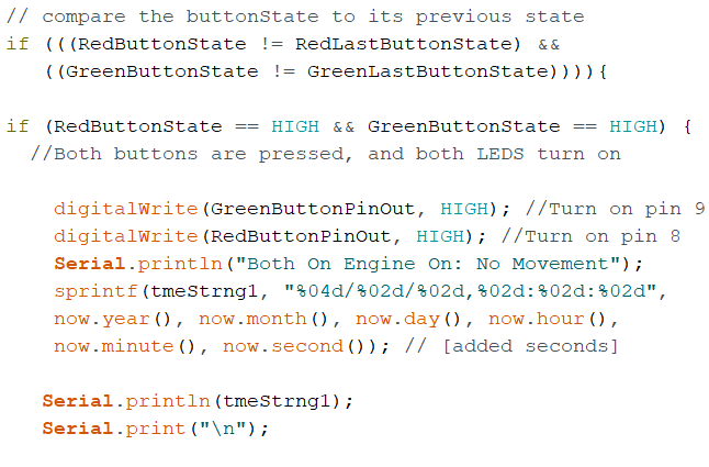
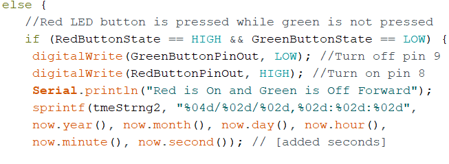
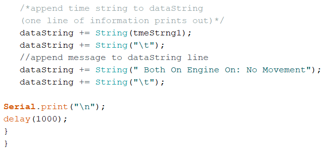
This same structure of code (if-else-if) was repeated for each of the 4 cases. What changed were, depending on the case, the button state positions (High/Low), the message printed, and the “tmeString” value.
The last case took place when both LEDs were off (switches were in a low position as seen below.
This would be the end of a cycle, so in this else block of code, it was important to set the last button state equal to the current button state.
Therefore, if the button(s) were pressed again the program would recognize that change and re-enter the cycle, checking for each case.
This would repeat until the power was turned off.
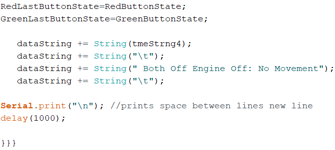
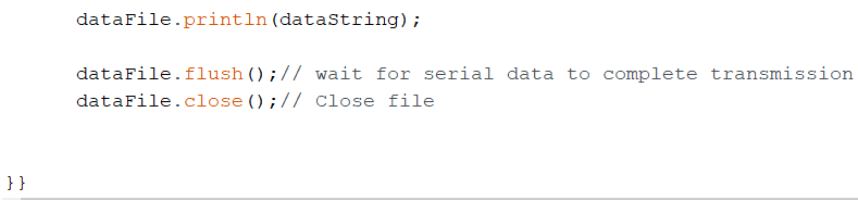
To conclude, the information that was appended to the “dataString” while the program was running, was printed to the text file located on the SD card.
Let’s take a look at the text file.
Final Results
Here are the results from the program above. When a switch combination occurs, the date and time, as well as the specific case, is recorded.
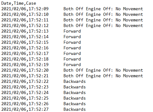
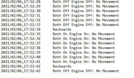
One problem that has not been solved is determining the duration a case takes place. Instead of documenting every second the case takes place and calculating the duration by sight, it would be beneficial to just know when the case started and ended, and ultimately, just how long the case took place.


2 Responses
I think this is a great post to have. I am always particularly intrigued by how code works. By adding these snippets of code, I can understand how everything collectively works together. It is also very cool seeing how the SD card is implemented into the code, considering that is something I have never done before.
Awesome Brandy, glad you were able to follow the code and learn something from this post!
The data logger has a built-in SD card. So, by implementing the SD card into the code, all information is directly stored in the associated file. This saves the hassle of trying to document data, especially long-term, by other means.
Thanks for your feedback!