Concept
For the final test circuit implementation, Version 1, the design was based on a suggestion from User John who offered a great idea on our Discussion’s page under the topic titled “Test Circuit.”
“… a test circuit could consist of two switches as input to the digital pins of an Arduino to simulate the output of the existing car’s controller. The code for the data logger could output the state of the switches with a time stamp. The test circuit would model the Car’s controller running the car’s motors.” – User John
By creating and testing the circuit, we could simulate the motion of the MROC and further determine the length of time the vehicle moved in a forward and backward direction.
Therefore, we decided to implement this concept into Version 1 of our final test circuit.
Test Circuit Diagram
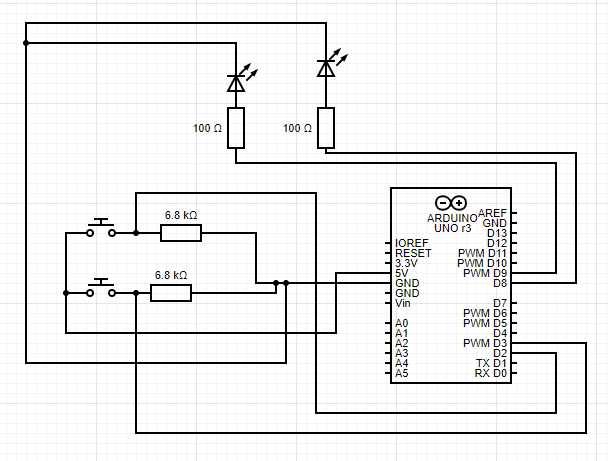
The test circuit version 1 uses the Arduino Nano. As seen in the diagram, it is made up of 2 LED diodes (red and green), 2 switches, and 4 resistors. Two 100 ohm resistors are in series with the LED, and the value of 100 ohms were chosen based on the LED specifications. The 6.8K ohm resistors are used as pull-down resistors to eliminate the output pin from being a floating pin.


Flow Chart
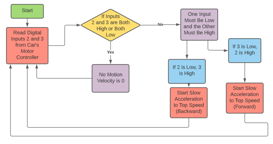
This is a flow chart that explains the functionality of the Test Circuit Diagram.
Build
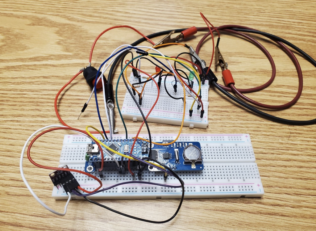
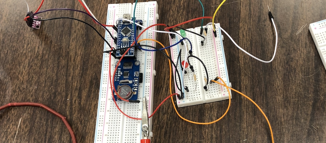
Based on the flow chart and circuit diagram, there are 2 switches that control the LEDs. Flipping the switch turns on the LED and it indicates whether the car is moving forward, backwards, or is stationary.


4 Responses
You should consider adding a flow chart.
A flow chart has been added. Thank you for your suggestion!
Can you provide a screenshot of the spreadsheet output from the test circuit or a copy of the spreadsheet?
Another post for the final test circuit was made that includes the programming and results! You can see a text file that depicts the outputs received.
Here is the link:
https://gbgdatalogger.ieeecbu.org/2021/01/19/data-logging-with-the-nano-shield-programming-and-results/