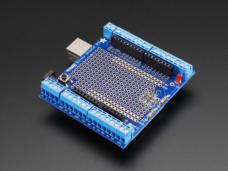
For my data logger design, I used the Arduino Uno Data Logger Shield/
The data logger shield board has pinholes and header pins that align directly with the Arduino Uno microcontroller for simple attachment.
The board arrives unassembled, however.
Therefore, to connect the Arduino and data logger together, header pins need to be soldered onto the data logger board. After soldering, you simply insert the data logger inside of the Arduino, and you are done with setup!
Assembly Process
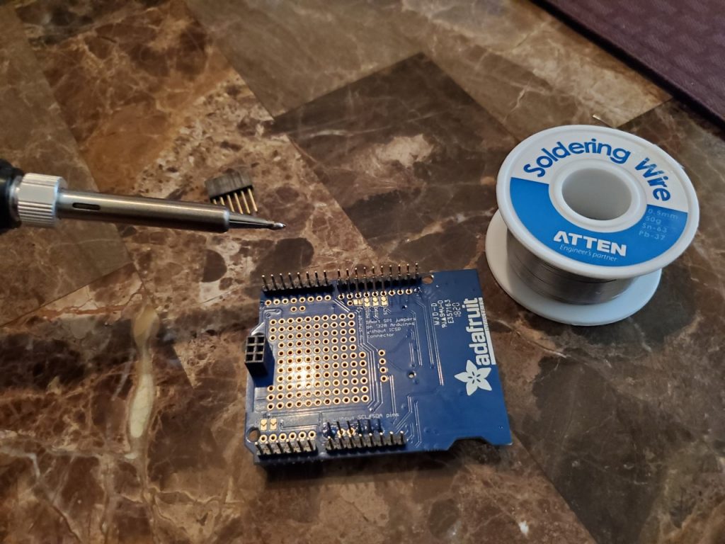
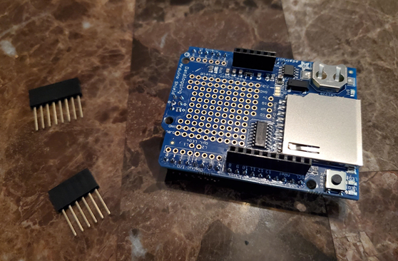
This is an image of the components that come with the data logger shield upon purchase.
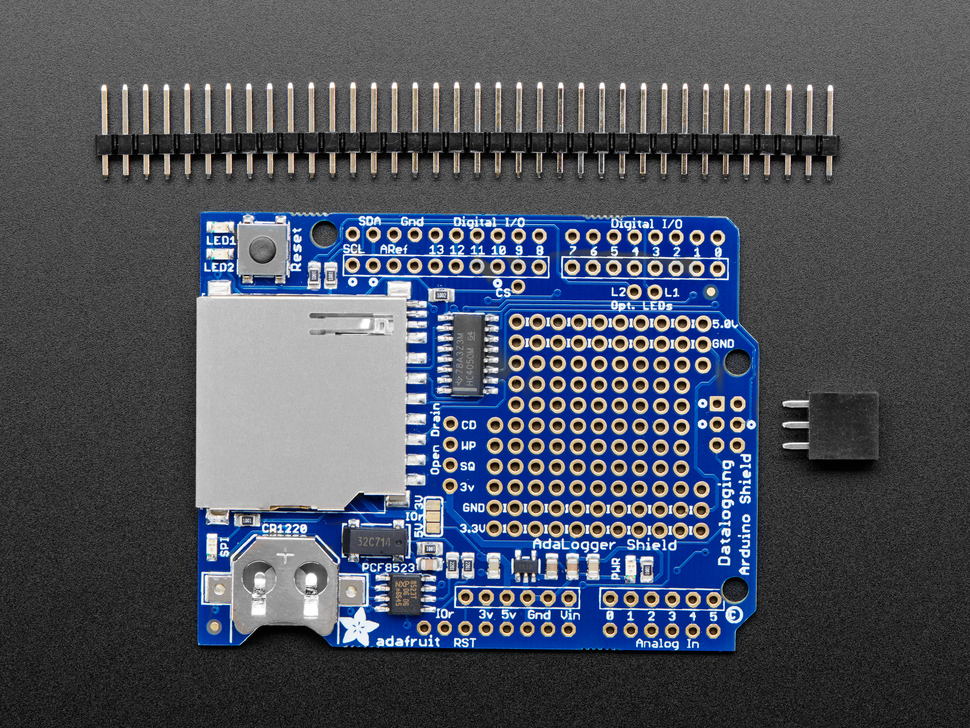
In addition to the data logger board, you receive a row of header pins (you cut the row into appropriate lengths) that insert into the Arduino. You also receive a 2×3 female header that aligns with the Arduino as well.
Small Problem
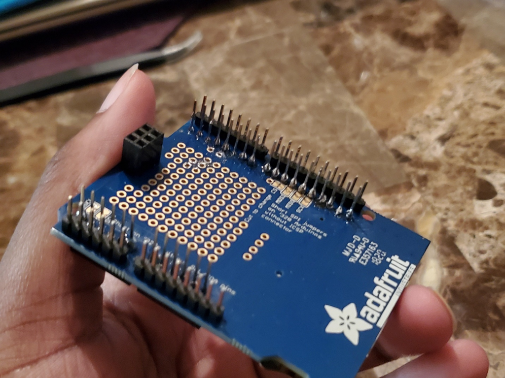
I ordered the data logger shield from Adafruit.com, and I was under the impression that all of the components needed for immediate use were included in the purchase. However, after receiving the logger, I soon realized that once the header pins were in place and the logger was connected to the Arduino, there would not be a means to connect a circuit to the shield as seen below.
Solution
I needed stacking headers!
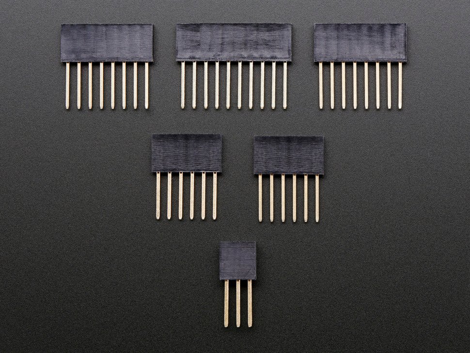
Stacking headers are used to connect jumper wires from a breadboard circuit to the shield.
Without them, I would be unable to connect a test circuit from a breadboard to the data logger shield.
Therefore, I made another Adafruit purchase and received the stacking headers a week later.
On to Soldering
As previously mentioned, the data logger shield arrives unassembled. To connect the data logger shield to the Arduino Uno and a breadboard circuit, header pins and stacking headers needed to be soldered onto the shield board.
I purchased a soldering kit on Amazon and was ready to solder!
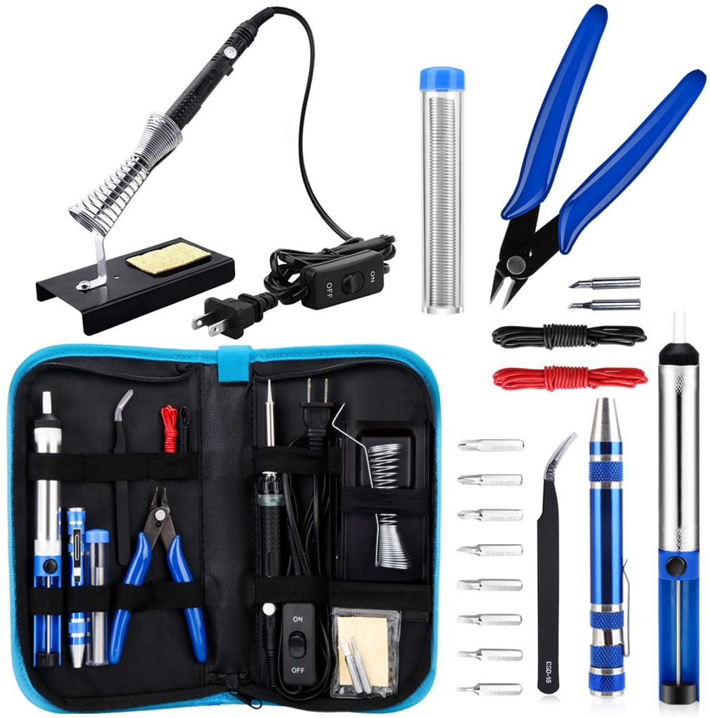
However, besides a small battery connection that resulted in overheating, I did not have much experience in the soldering department.
Learn How to Solder
Fortunately, Min has had some experience in the area and was happy to teach me.
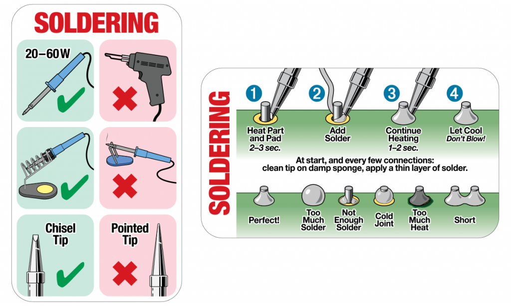
We had a quick lesson, and he expressed the significance of safety when using a soldering iron. Min also explained how it was important to place solder directly on the pin and to not let the solder come into contact with other pins. This is because solder is like a gluable extension cord.
By soldering a component, we provide an electrical extension to something else. In the stacking header case, we want to make exact connections. If solder attaches to something it shouldn’t then that can result in not only unneeded connections, but also device failure such as shorting, overheating, and much worse. For example, you could be providing an additional 5 volts of power to a place that is deemed for grounding.
After learning how to solder, I began soldering the headers onto the data logger shield.
Solder the Header Pins
To solder the headers, they needed to be cut to their appropriate lengths that aligned with the correct groups of pin lengths for the Arduino.
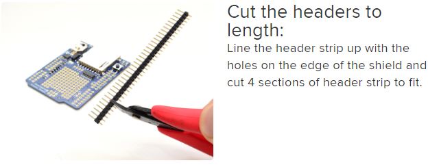
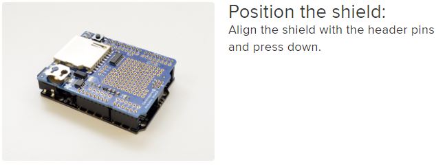
After that, the headers were placed inside of their respective pins on the Arduino Uno and the data logger board was placed on top. Then it was time to begin soldering.
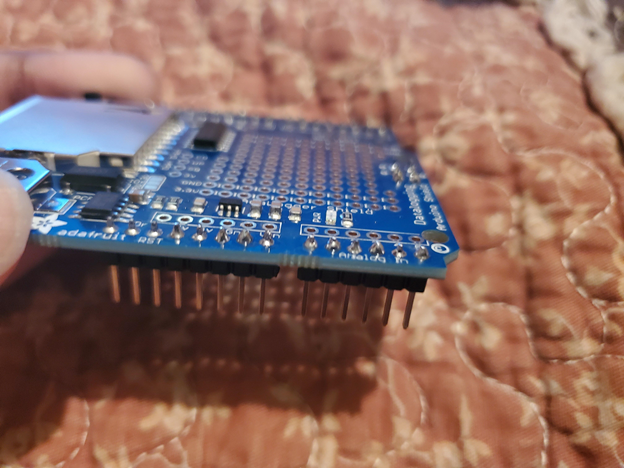
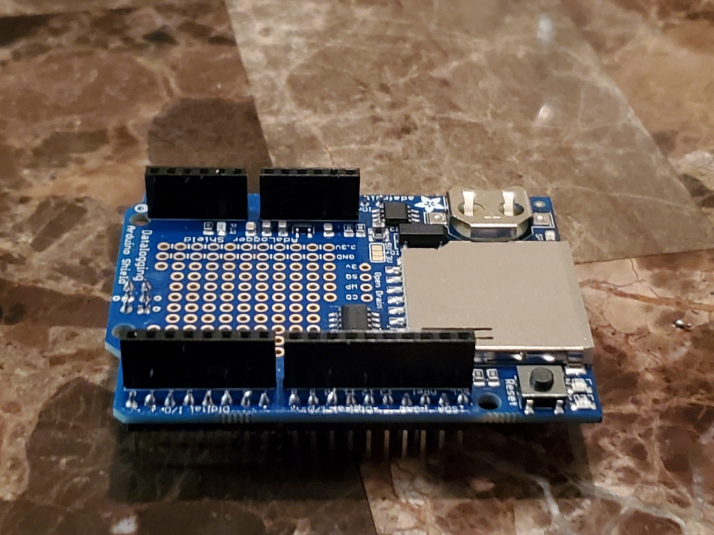
Here are my results:
Solder the Stacking Headers
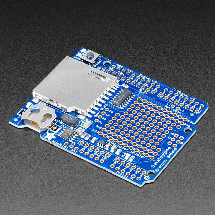
Soldering the stacking headers was done in a similar fashion as the header pins. However, this involved flipping the data logger board to the opposite side as shown in the image below. This was because jumper wires are inserted into the female connections from an external breadboard circuit, and installing the stacking headers upside down would complicate the connection process.
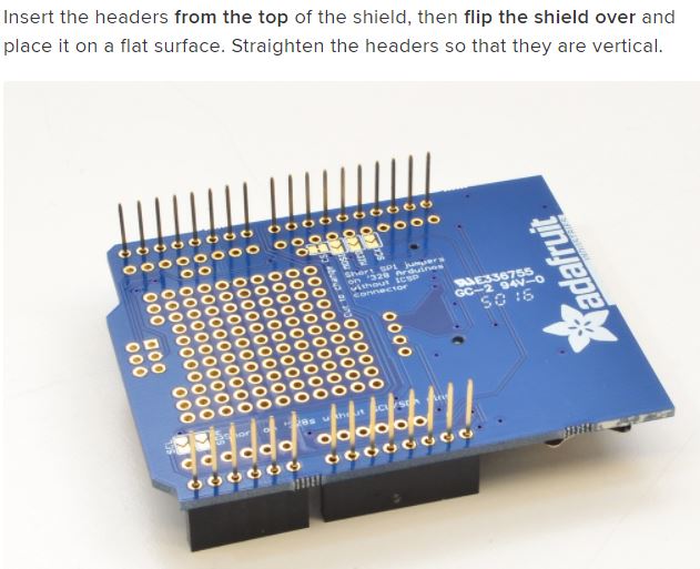
Upon completing those initial actions, it was time to begin soldering each pin to its respective pinhole on the logger board.
Soldering was fun, but it is not always as simple as it may seem. Precision and accuracy are important.
I say this because it is very easy to make mistakes. The data logger device is small, and this means that the chips and pinholes are even smaller and very close together in a layout. Thus, it is easy to make mistakes and get solder in places that there should not be solder.
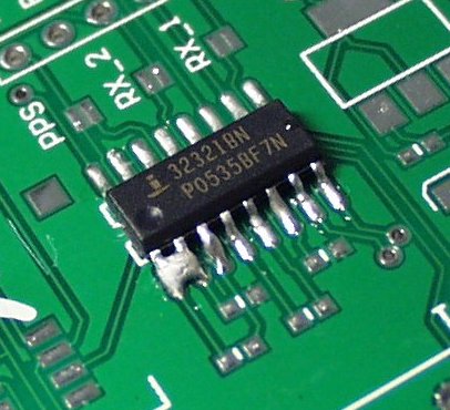
Here is an example of a mistake I made during the process:
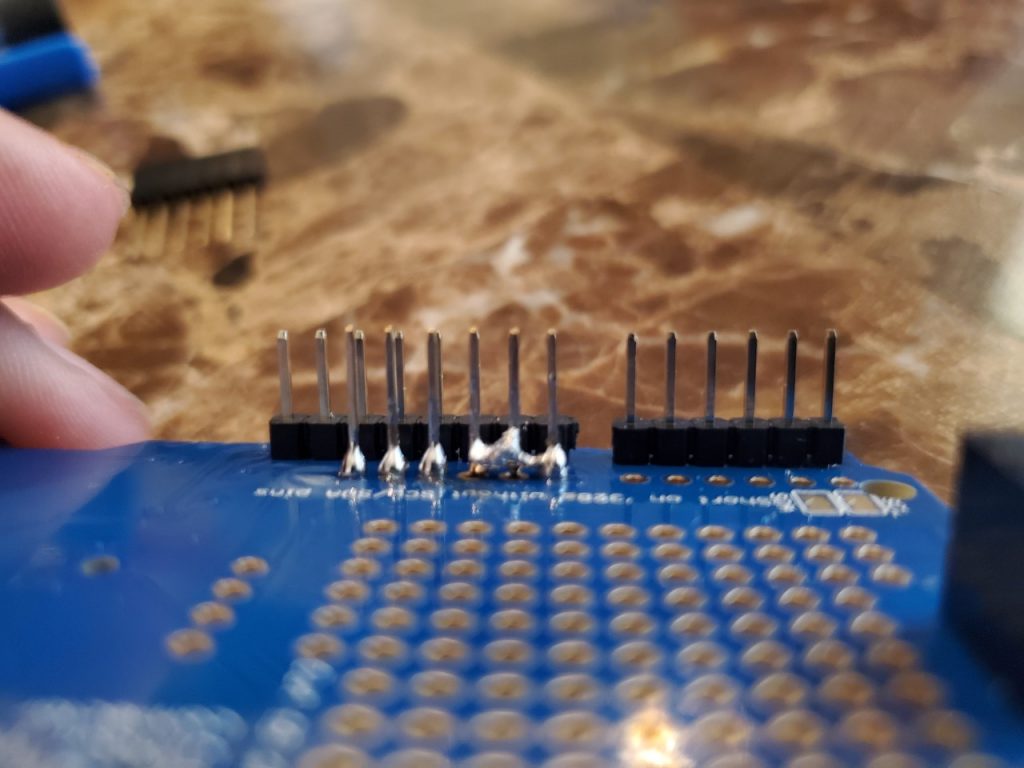
I soldered 3 pins together which is very bad. It can become worse if not corrected prior to circuit and power connections.
Removing Solder
As mentioned before, solder is like strong glue that dries quickly. Once it dries, the solder can be removed by reheating, but the process is not always simple.
To fix my errors, I used the soldering iron to reheat and melt the solder. Then I used a suction pump to extract the melted solder. This process must be done quickly and in unison because the solder dries fast!
Soldering Iron 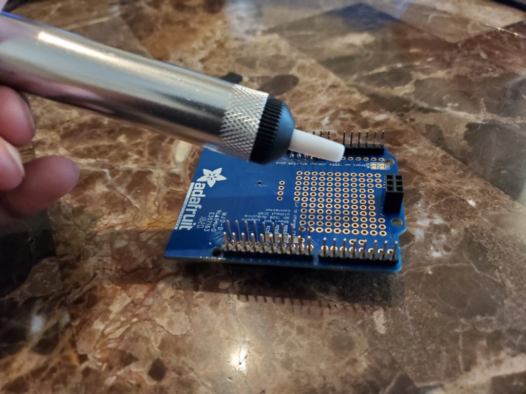
Suction for Removal
This is an image after I removed the solder from the pins.
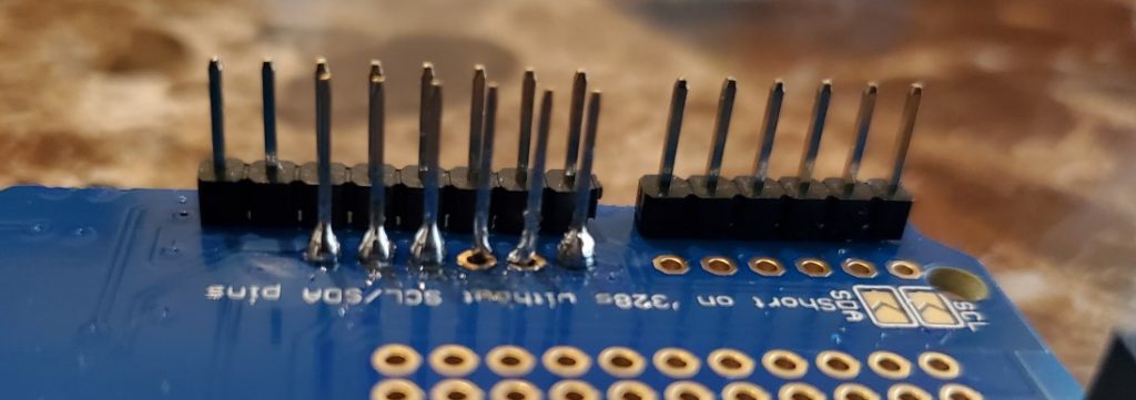
I was in a tough position, but the next goal was to solder those two individual pins as accurately as possible without connecting them again.
End Results
Alas, I prevailed and was able to proceed with soldering the rest of the stacking header pins.
These are the final results after completing the soldering process.
Complete the Assembly
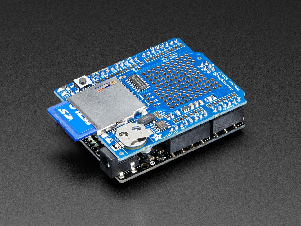
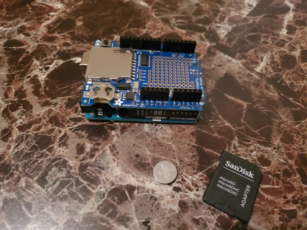
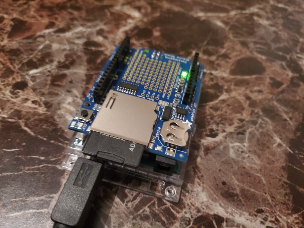
After soldering the header and stacking header pins, all there was left to do was insert the logger board into the Arduino. From there, a 3-volt coin-cell battery was inserted to provide power to the RTC (Real Time Clock Module), and the SD card was inserted into its respective port.
Apply Power
The USB cable was inserted into the assembled Arduino Uno data logger shield.
Now, it was time to create a test circuit, using a few sensors, and to program the logger to collect and store data.