

After assembling the device, the next step was to make a test circuit so I could begin to record data.
Usually, when someone collects data, there are variables or conditions that change over time.
For UTHSC, the group wanted a data logger that could ultimately keep track of the date and time, and also document when a child was driving an MROC in a given direction and the duration the child drove in said direction.
For the data and time aspect, the data logger’s built-in RTC (Real Time Clock) would keep track of that. However, I needed a few sensors to act as variables and simulate motion.
After careful thought, I decided to implement an AM2320 sensor, a photocell resistor, and an LED diode into the circuit.
Concept
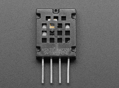
The AM2320 sensor measures temperature and humidity.
I wanted to use the sensor as an additional means of measuring fluctuating data and precision. For further analysis, I could, perhaps, plot the temperature and humidity values in Excel and create a graph.
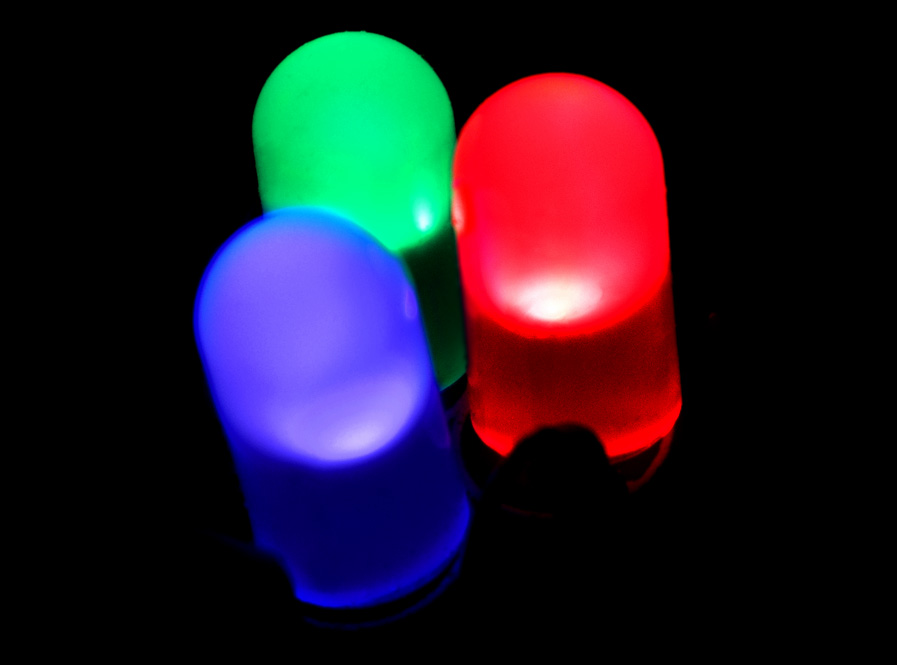
Photocell and LED
A photocell (photocell resistor) is a resistor that changes its resistance value depending on how much light is shining on it. In choosing these two components, the idea was to program the circuit such that the LED would turn on when the value of the photocell decreased to below a certain value and when the value increased to above a certain integer, the LED would turn off.
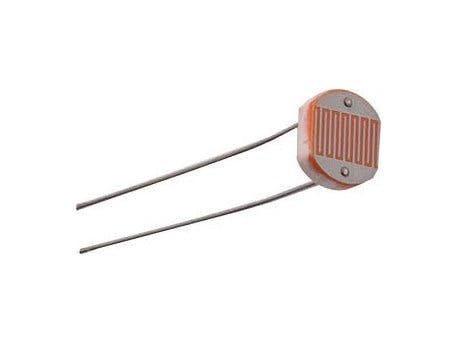
In short, this was something like an automatic night light. When the environment was dark, the LED would turn on. In the presence of light, the LED would turn off.
For GBG and UTHSC’s data logging needs, I associated the LED being on/off with the forward and backwards motion of the MROC.
Problem
I had a way to simulate forward and backward motion, but I had difficulty determining a way to account for no motion.
However, I proceeded to construct the circuit in hopes to find a solution along the way.
Circuit Construction
To create the circuit, I began by constructing and programming two smaller circuits. A circuit with the AM2320, and another with the photocell and LED.
Then I combined the two.
I wanted to have each sensor/component working on its own before I attempted to program one big circuit. I find it easier to work in small sections when possible.
This post will demonstrate the setup for the circuits. The next post will touch on programming.
AM2320
All connection instructions and working code are available on the Adafruit website. You purchase the chip or take a look at the steps here: https://learn.adafruit.com/adafruit-am2320-temperature-humidity-i2c-sensor/overview
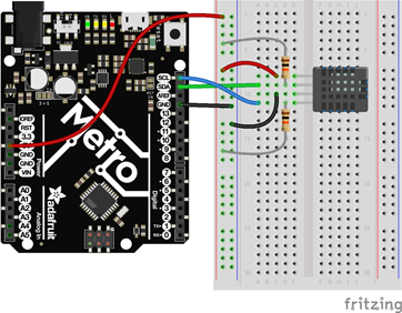
Wire Schematic and Characteristic Chart
Here are the pinouts for the AM2320 chip:
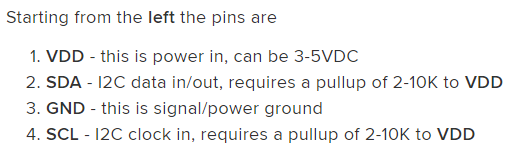
The connection calls for two 10k ohm resistors to connect to the SDA and SCL pins, respectively. I used two sets of 20k ohm resistors in parallel to obtain 10k ohms.
This is the characteristic chart:
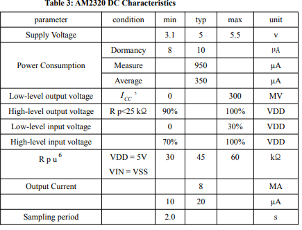
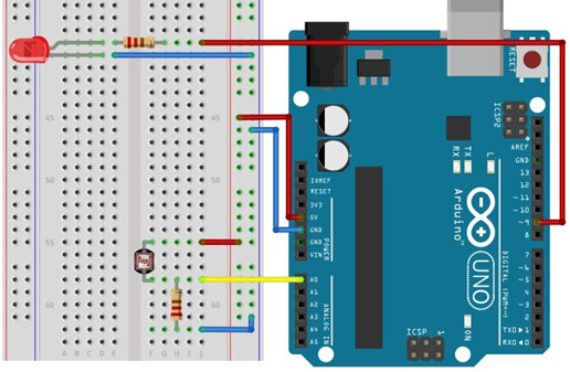
Photo Cell and Led Wire Schematic
This image depicts a visual configuration of the circuit.
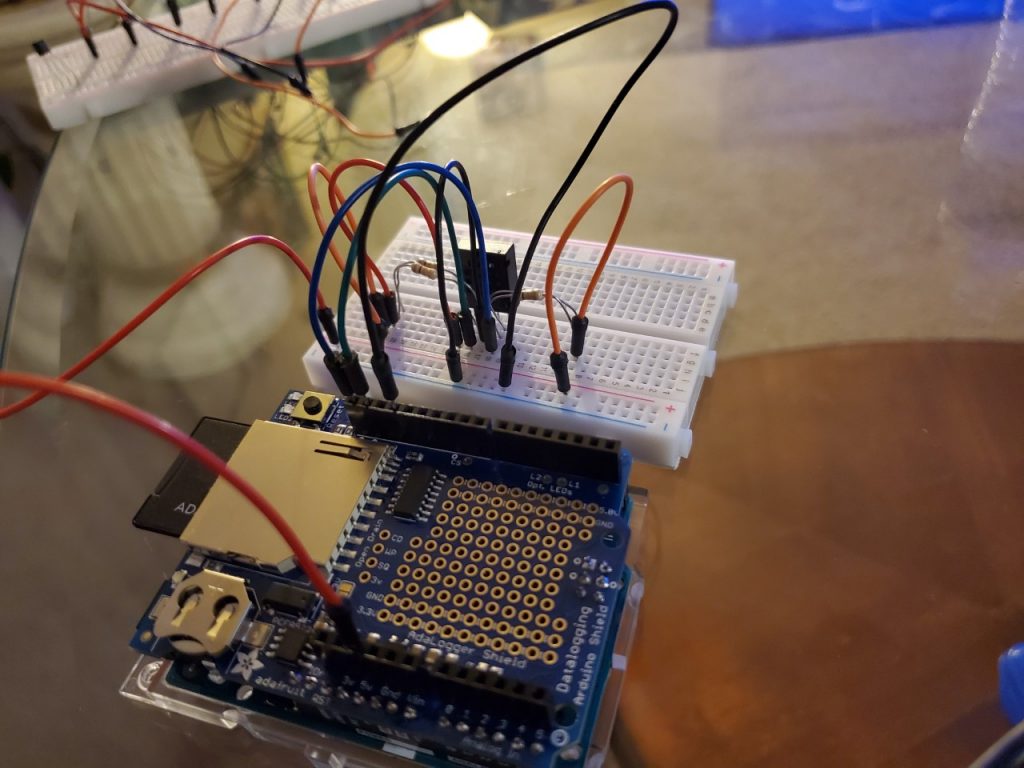
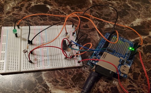
Final Circuit
Here is a look at the final circuit containing the AM2320 sensor, the photocell, and LED components:
The next post will involve the programming process for the test circuit.


One Response
I do not know if it is possible to insert a video in the blog, but adding a brief video might help you to more fully illustrate how the LED sensors are being used here.